Synthesis
Is the process step to transform the technology independent register-transfer level (RTL) description of a system into a technology dependent netlist using a specific technology cell library.
Most Electronic Design Automation Synthesis tools support translation from designs written in SystemVerilog, Verilog, VHDL or a mixture of them.
Synthesis can be defined to optimise the output for different criteria, for example area use, timing, allowable loads on signals, the movement or merging of registers, or to control the amount of time a synthesis takes. Synthesis attributes and directives can be included in the source, for example to direct the synthesis to perform or not certain actions when synthesizing a design. Synthesis Attributes, such as expected arrival time of a signal at an input port, and Constraints, such as maximum input to output delay, are added to direct the synthesis.
Synthesis can be initiated from within an Integrated Design Environment by the designer or via a command interface that can be used to make scripts and automation of the process.
Projects Using This Design Flow
megaSoC
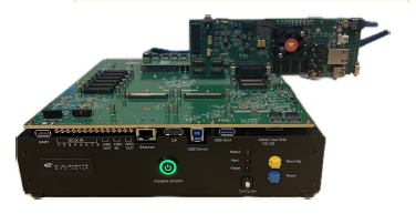
Reference Design Comparison Table
This table will let you compare this reference design with others on SoC Labs| Title | megaSoC | milliSoC |
|---|---|---|
| Class | Complex | Mid-range |
| Reference Design | MegaSoC | TSRI/SoC Labs |
| Staffing | Academic team | Academic + dedicated post doc |
| Time Scales | 6 months to 1 year | 1+ years |
| Model Forms | Trial of processing element | |
| Tape Out / Package and Board Costs | >£50k | £25k-£50k |
| Processor(s) | A53 | M55/U55 |
| Processor(s) (speed) | > 800 Mhz | 250-800Mhz |
| Data Rates / On Chip Comms | <2.5 Gbps | 10-80 Gbps |
| Data Rates / Off Chip Comms | <50 Mbps | 0.1-0.8 Gbps |
| On Chip Memory Requirements | 32KB to multiple MB | 2MB+ |
| Virtual Prototype Environment | HAPS | MPS3 |
| Tape Out Node | 28nm | 28nm |
Related Projects and Workflows
This section details the following: the core reference design, the initial project that led to the definition of the reference design, and any additional projects that extend the reference design for new or additional applications. It also defines the related example workflows for the front end Architectural and Behavioural design stages, and the back end Logical and Physical design stages. Front end Behavioural design are usually accomplished with FPGA environments and tool chains, back end Physical design requires technology specific design rules and EDA tool suites.
Related Project Milestones
| Project | Name | Target Date | Completed Date | Description |
|---|---|---|---|---|
| Project Milestone Overview example | Synthesis (97) |